|
Rodney M. Goodman B.Sc., Ph.D., C.Eng., SMIEEE, FIEE.The Silicon Active Skin Research
Authors: Vincent Koosh, Dave
Babcock, Rodney Goodman, Tom Tsao, Fukang Jiang, X.Q. Wang, Y.C.
Tai, J.
Kim ,C.M. Ho Motivation and Aims: Techniques for reducing the surface drag on modern
transportation devices such as planes or high speed trains are highly
sought after. Even drag reduction on the order of 5% could lead
to enormous savings in fuel costs. Until recently, only passive
techniques, such as riblets, were available for such purpose. Recent
technological advances in circuit and MEMS techniques and greater
understanding of the problem allows active techniques which monitor
the flow and actively deform the skin based on flow conditions to
be pursued. We seek to build a fully integrated neural-networked
MEMS system to distributedly sense the shear stress, to design neural
controller with feedback mechanism, and to efficiently actuate robust
micro actuators for surface stress reduction. Research: Micro Surface Shear Stress Sensor: A device capable of detecting fluctuating surface shear stress is essential for the control of wall shear stress experiment. However, the heat transfer to the substrate has always been a handicap of the conventional hot-film type surface shear stress sensors for several decades. For measurements in air, the sensitivity is close to zero because of the low heat capacity of air. By using surface micromachining technology, a vacuum chamber is placed under the heating element. This cavity significantly decreases the heat loss to the substrate (Liu et al., 1994, Huang et al 1995 & 1996). The typical sensitivity of the sensor with a cavity underneath is 15 mV/Pa, which is about one order of magnitude higher than that without a cavity.
In a turbulent boundary layer, the high speed streaks are distributed in a two-dimensional domain. A sensor array containing a large number of sensors is needed for mapping the skin-friction distribution. A surface shear-stress imaging chip was developed for this purpose (Jiang et al 1996). Each imaging chip consists of 85 micro sensors. On the chip, the sensors are arranged into multiple arrays, and the spacing between consecutive sensors is designed to provide adequate spatial resolution in measuring the near-wall streamwise streaks.
Micro Actuator: In flow control problems, we need actuators which are able to provide about one mm off-plane motion and about milli-Newton force per mm 2 for sustaining the wind loading. These requirements were several orders of magnitude higher than that available from existing micro actuators. In order to accomplish these stringent performances, a flap type actuator was chosen for the design (Liu et al 1995). electromagnetic force was chosen to drive the actuator. Both surface micromachined and bulk micromachined actuators have been developed. Interaction between Actuator and Streamwise Vortices: How the motion of the streamwise vortices affected by the actuator and eventually achieving skin-friction reduction is a key issue for interactive wall flow control. Experiments have been carried out to investigate the interaction between a single high shear-stress streak and a micromachined actuator. Experiments are performed for different combinations of actuator frequency (w) and maximum tip height (d). As expected, the non-linear interaction between a moving surface and a vortex is complex. On the other hand, skin-friction reduction can be achieved if the actuation is properly applied. The reduction is a function of the product of w and d. Since the product of w and d is a measurement of the transverse velocity of the actuator flap, this result indicates that the amount of shear stress reduction is directly related to the transport of high-speed fluid away from the surface by the vertical motion actuator.
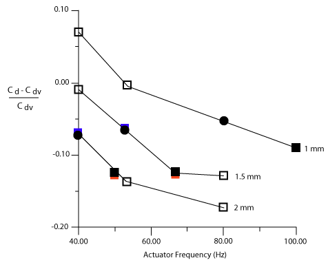
Variation of the shear stress coefficient, C DN , with actuator frequency, w, and maximum actuator tip height, d. The solid O markers correspond to an w*d of 80 and the solid square markers correspond to an w*d of 100. Numerical Experiments of Neural Network
Based Control This neural controller was applied in an on-line adaptive inverse model scheme, with the desired inputs being a fractional reduction of the local surface shear stress from the previous time step and the outputs being the necessary actuation to achieve this reduction. We observed that the relative magnitudes of the weights did not change (indicating the approximate derivative pattern is preserved) but that the absolute magnitudes fluctuated during the course of the simulation. Therefore the input weights were fixed to compute an approximation to the derivative leaving only a gain and bias for each layer to adapt as the simulation progresses.
Applying this control network and employing blowing and suction at the wall based only on the wall-shear stresses in the spanwise direction, was shown to reduce the skin friction by as much as 20% in direct numerical simulations of a low-Reynolds number turbulent channel flow . Also, a stable pattern was observed in the distribution of weights associated with the neural network. This allowed them to derive a simple control scheme that produced the same amount of drag reduction. This simple control scheme generates optimum wall blowing and suction proportional to a local sum of the wall-shear stress in the spanwise direction. The distribution of corresponding weights is simple and localized, thus making real implementation relatively easy.
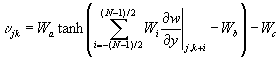
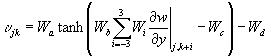
Although the work by Lee et al. (1996) is a significant improvement over earlier approaches that require velocity information within the flow, there are a number technical issues before such a control scheme can be implemented in real practice. Among other things, precise control of blowing and suction distributed over a surface in a laboratory test is still too difficult to implement. Analog VLSI Circuits The previous work on the application of neural networks to turbulence control of drag reduction showed that a neural network could be trained to reduce drag. The network that was trained was a standard two-layer feedforward network with inputs of du/dy and dw/dy. However, during the training it was discovered that only the dw/dy inputs impacted network performance. The function implemented by the network is, where j and k denote the numerical grid point in the streamwise and spanwise directions. During the training of the network it was discovered that the weight values settled and then remained constant relative to each other but with the same scale factor applied for each. The weight pattern was found to be given by . The meaning of this weight pattern was discovered to be that the network implemented a scaled spanwise derivative of dw/dy. Thus it was possible to implement a new network as . Where an input template size of 7 is chosen. Training of this network showed that Wc and Wd were negligible, and that Wa and Wb varied significantly but their product remained relatively constant. It was further discovered that a linear network produced similar results to the nonlinear one, but the standard deviation of the learned weights was worse than with the nonlinear network.
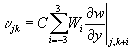
For the linear network it was seen that the same weight pattern could be used, and that the constant scale factor could be chosen such that the root-mean-squared value of the actuation was kept at 0.15 ut . Thus,
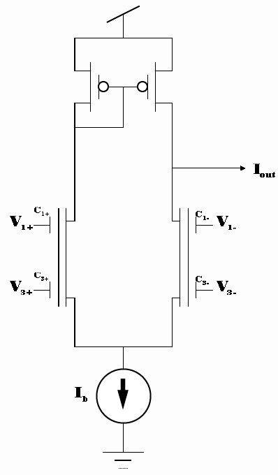
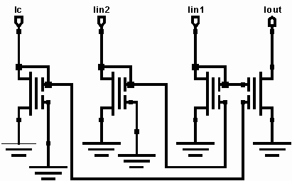
for a single row of actuators, and K is determined by the parameters of the flow. In hardware, we will implement a single row of dw/dy sensors that trigger a single row of actuators. Thus the circuits used to control the actuations must be able to perform the aforementioned computations. The dw/dy sensors come from constant temperature circuits that place them in a Wheatstone bridge configuration. The output is a voltage related to dw/dy. The first thing that must be accomplished is the summing and weighting of these voltages. The following circuit is used for this purpose.
The output of this circuit is given by
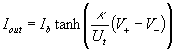
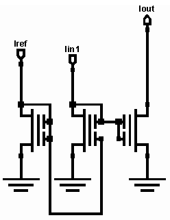
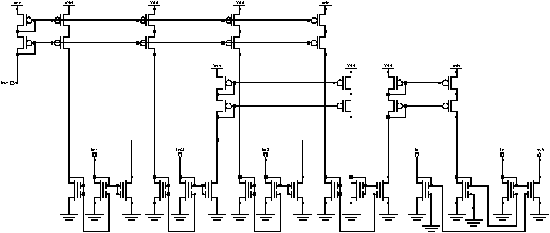
Thus, the weight pattern can be implemented by choosing the capacitor ratios to match the equation for Wj given above. Furthermore, the constant k/Ut can be varied from a value of about 20 to about 40. This serves to act as the variable gain stage that implements the gain Wb within the tanh function. One benefit of the weight pattern is that for an input template of size 7, only 4 sensors are actually needed since the even weights are zero and nullify those sensors. To implement the linear function instead of the tanh, we can simply increase CT to reduce the inputs until we are in the linear portion of the tanh, then we can provide gain afterwards. The rest of the signal processing is done in current mode since the previous stage, which does weight multiplication and summing, outputs a current. Both the nonlinear network and the linear one require the output of the weighting and summing network to be scaled and normalized by the rms value of the other sensor arrays. The building blocks of the rms circuit are shown below.
These building blocks are placed together to provide the rms normalization and scaling circuit given below.
The above circuit performs the necessary normalization. We can also actively control the IC input to act as the external gain Wa which is required by our functions. These circuits form the core of the signal processing circuitry necessary to implement the neural networks that have only previously been implemented in software. Other circuits which are not shown are required for impedance matching between the stages, but they do not contribute to the mathematical function implementation. The final stage of processing is a current amplification stage which amplifies the currents from the small levels which are used for the analog signal processing to the larger current levels necessary to drive the actuators. This is a fixed gain stage for all signal currents to the actuators. These circuits are all analog and perform the computations required in real-time. The nonlinear network requires actively controlling two inputs, while the linear network only requires setting IC for the flow conditions, and the normalization circuitry provides the rest of the signal gain adjustment. Achievements:
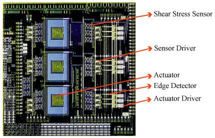
M3 System for
Shear Stress Reduction:To integrate microsensors, microelectronics
and microactuators on a chip is possible, yet is not a trivial task.
We have fabricated an M3 system for shear stress
reduction. On this 1 cm by 1 cm die, 18 micro shear stress sensors,
3 micro flap actuators as well as circuits for logic, sensor driver
and actuator drivers are monolithically integrated. It is not fully
functional yet, but experience gained through this exercise is extremely
valuable for us to proceed toward a working system.
An M3 System for Shear Stress Reduction
|
|||||

 The
active skin is also a multi-disciplinary project, involving researchers
in the fields of MEMS, Fluid Dynamics, Control Theory, and Electronics.
The objective of the project is to integrate MEMS sensors and actuators,
neural network sensory processing, and control circuits all on the
same silicon substrate to form a “smart skin”, capable
of reducing drag on an aircraft wing. In nature, such a system of
actuators controlled by biological neural networks is believed to
exist in the shark. The drag reduction implemented by this “smart
skin” contributes to the high speed of the shark, which is
the fastest creature in the ocean.
The
active skin is also a multi-disciplinary project, involving researchers
in the fields of MEMS, Fluid Dynamics, Control Theory, and Electronics.
The objective of the project is to integrate MEMS sensors and actuators,
neural network sensory processing, and control circuits all on the
same silicon substrate to form a “smart skin”, capable
of reducing drag on an aircraft wing. In nature, such a system of
actuators controlled by biological neural networks is believed to
exist in the shark. The drag reduction implemented by this “smart
skin” contributes to the high speed of the shark, which is
the fastest creature in the ocean. 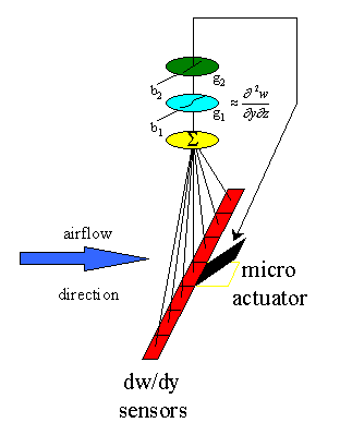
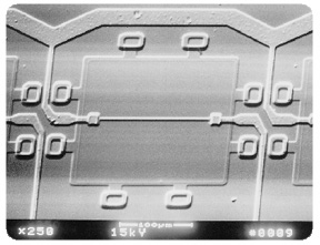 (a)
a single micro shear-stress sensor
(a)
a single micro shear-stress sensor 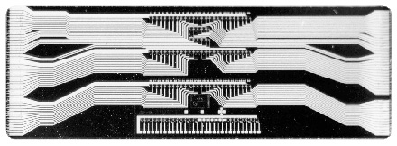 (b)
a sensor array
(b)
a sensor array